WS2812 Wifi display

maxresdefault 12

WS2812 Wifi display

Hello, friends welcome to my blog. In this blog, we learn about how to make a wi-fi display by using a WS-2812 strip display.

Parts required:

  1. Led strip 2812 https://koshielectronics.com/product/ws2812-led-strip/
  2. Pixel wi-fi controller https://koshielectronics.com/product/pixel-led-wifi-display-controller/
  3. Power supply https://koshielectronics.com/product/5-volt-20-amp-smps/

Wiring

1619441482315
(a)
1619441482310
(b)

Software : koshi Wi-fi

Steps to do:

Step1 When you buy the controller, you will get an app in the name of koshi wi-fi.
1619441482263

Step 2 Open the wi-fi, you will see the wi-fi name koshi connect to that. After that enter the password koshi1234 and connect to this wi-fi.

1619441482306

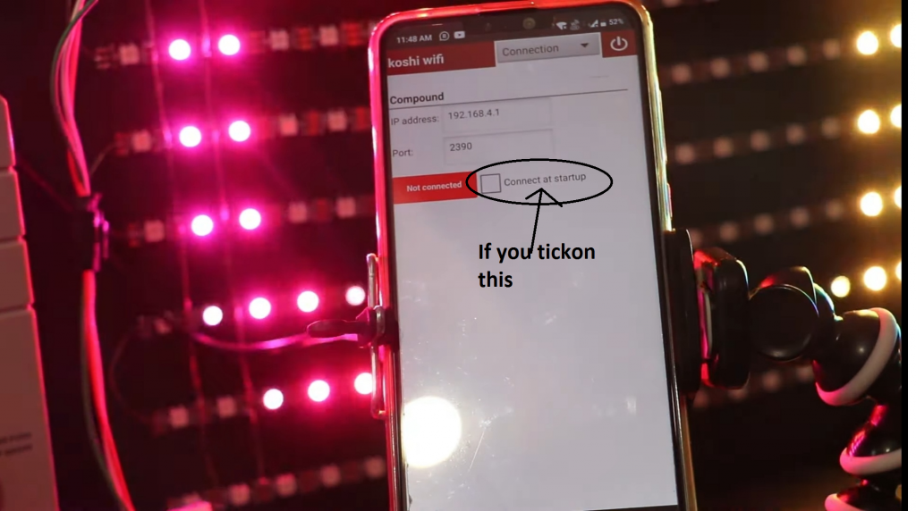
Step 3 Go to the application and click on connected.

Step 4 If you tick on the connect at start up what happened that when you close the app and after that when you next time open your app, your app will automatically connected. You don’t need to connect again.
Untitled 4

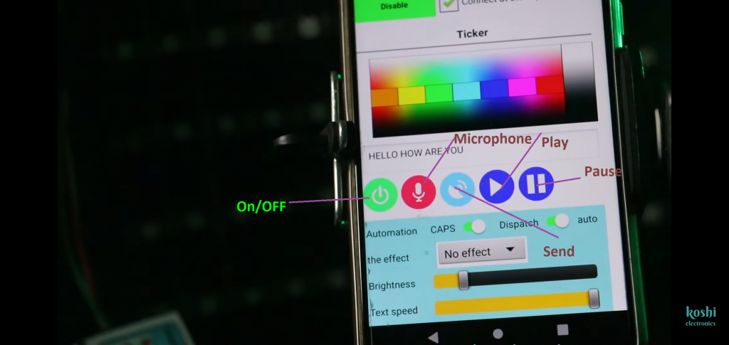
Step 5 Now lets talk about the buttons given on the app. First button which is green in colour is ON/OFF button. Through this display can be off/on.2nd button is of microphone. Whatever you speak that’s display on the screen.In this we have two features first Caps and another auto.
Untitled 4.png 1 4

Step 6 If you click on auto and speak, we see that the text is moving in small letter. When you off the auto and click on caps then speak again, we see that text on the board is moving in the capital letter. If you off the both then nothing is moving in the display untill or unless you click on send button which is blue in colour. When you not click on that button the text which you enter previously that text is running on the board continuously.

Untitled.png 3

Step 7 Now you see the next features which is Brightness, Text speed and Effect change.You can set all these according to you as you want.

Untitled.png 4

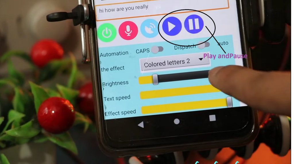
Step 8 Next button is play and pause button. If you enter the text and want to stop it then click on pause button. Here we have six colour according to you, you can set the effect.
Untitled.png 5

Step 9 At the top right of the screen we see the power button, through this we can exist from the screen .Another option is of clock .If you want to run the clock firstly clear the text. For this what you have to do is select text option ,clear the text screen and then click on send. We see that on the screen timer is running. You can also pause the timer by clicking on pause button.

Untitled.png6
(a)
WS2812 Wifi display
(b)

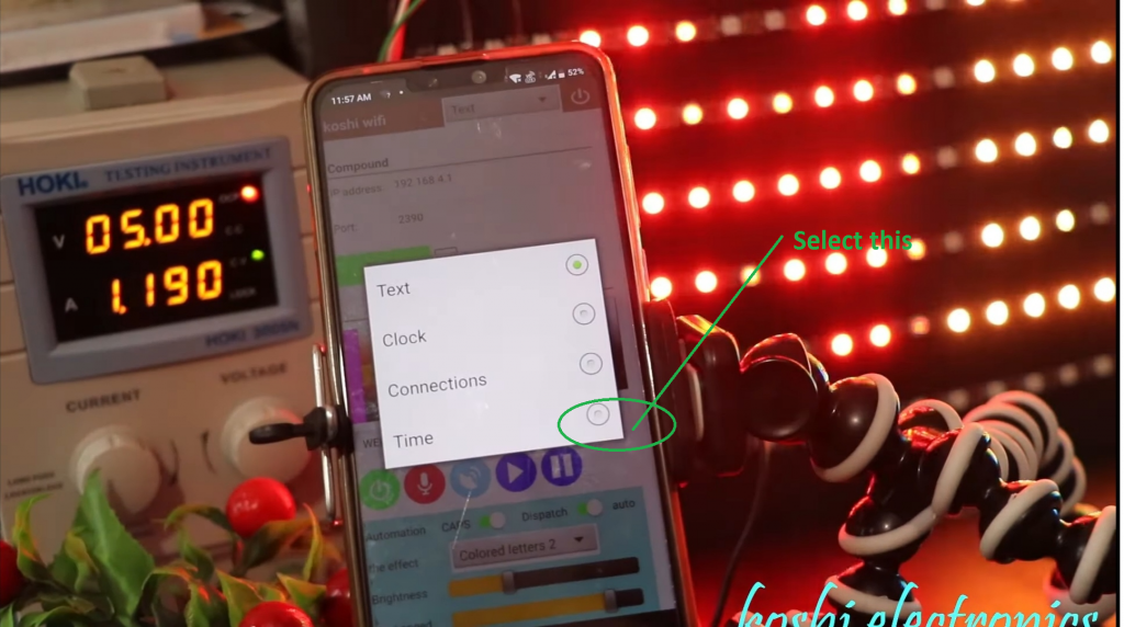
Step 10 Next is the time option. If you want to ON/OFF the display you can set the time. In mode1 you can set the time according to you and click on turn off and in mode 2 again set the time and click on turn on then click on save. As you have seen that the time which you set according to that function will perform.

1619441482290
(a)
Untitled 1.png6 1

video tutorial -WS2812 Wifi display

How to make pixel led message display

maxresdefault 4

How to make pixel led message display

I built an 8×30 LED-Matrix pixel led message display with the great RGB LEDs WS2811 The whole matrix is controlled only by one pin of an Arduino Uno

Parts required

Wiring of How to make pixel led message display

How to make pixel led message display

Code for Arduino

// Adafruit_NeoMatrix example for single NeoPixel Shield.


#include <Adafruit_GFX.h>
#include <Adafruit_NeoMatrix.h>
#include <Adafruit_NeoPixel.h>
#ifndef PSTR
 #define PSTR // Make Arduino Due happy
#endif

#define PIN 6

// MATRIX DECLARATION:
// Parameter 1 = width of NeoPixel matrix
// Parameter 2 = height of matrix
// Parameter 3 = pin number (most are valid)
// Parameter 4 = matrix layout flags, add together as needed:
//   NEO_MATRIX_TOP, NEO_MATRIX_BOTTOM, NEO_MATRIX_LEFT, NEO_MATRIX_RIGHT:
//     Position of the FIRST LED in the matrix; pick two, e.g.
//     NEO_MATRIX_TOP + NEO_MATRIX_LEFT for the top-left corner.
//   NEO_MATRIX_ROWS, NEO_MATRIX_COLUMNS: LEDs are arranged in horizontal
//     rows or in vertical columns, respectively; pick one or the other.
//   NEO_MATRIX_PROGRESSIVE, NEO_MATRIX_ZIGZAG: all rows/columns proceed
//     in the same order, or alternate lines reverse direction; pick one.
//   See example below for these values in action.
// Parameter 5 = pixel type flags, add together as needed:
//   NEO_KHZ800  800 KHz bitstream (most NeoPixel products w/WS2812 LEDs)
//   NEO_KHZ400  400 KHz (classic 'v1' (not v2) FLORA pixels, WS2811 drivers)
//   NEO_GRB     Pixels are wired for GRB bitstream (most NeoPixel products)
//   NEO_RGB     Pixels are wired for RGB bitstream (v1 FLORA pixels, not v2)


// Example for NeoPixel Shield.  In this application we'd like to use it
// as a 5x8 tall matrix, with the USB port positioned at the top of the
// Arduino.  When held that way, the first pixel is at the top right, and
// lines are arranged in columns, progressive order.  The shield uses
// 800 KHz (v2) pixels that expect GRB color data.
Adafruit_NeoMatrix matrix = Adafruit_NeoMatrix(30, 8, PIN,
  NEO_MATRIX_TOP     + NEO_MATRIX_LEFT +
  NEO_MATRIX_COLUMNS + NEO_MATRIX_ZIGZAG,
  NEO_GRB            + NEO_KHZ800);

const uint16_t colors[] = {
  matrix.Color(255, 0, 0), matrix.Color(0, 255, 0), matrix.Color(0, 0, 255) };

void setup() {
  matrix.begin();
  matrix.setTextWrap(false);
  matrix.setBrightness(40);
  matrix.setTextColor(colors[0]);
}

int x    = matrix.width();
int pass = 0;

void loop() {
  matrix.fillScreen(0);
  matrix.setCursor(x, 0);
  matrix.print(F("WELCOME TO MY ELECTRONICS RAVI YOUTUBE CHANNEL "));
  if(--x < -400) {
    x = matrix.width();
    if(++pass >= 3) pass = 0;
    matrix.setTextColor(colors[pass]);
  }
  matrix.show();
  delay(100);
}