how to make pixel led sd card type controller using arduino

pixel led SD card type controller using Arduino

In this projects, we learn about

how to make Pixel led SD card controller using Arduino

Parts required

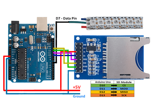
Wiring

Code for How to make pixel led Sd card controller using Arduino

#include "FastLED.h" // add fastled library
#include    // add sdfat library


#define NUM_LEDS 225  // total leds  
#define DATA_PIN 7    // led data pin
CRGB leds[NUM_LEDS];

//SD chip select pin
const uint8_t chipSelect = SS; //chipSelect = 10;

SdFat sd;
SdFile file;


void setup() { 
      // Uncomment/edit one of the following lines for your leds arrangement.
      // FastLED.addLeds<TM1803, DATA_PIN, RGB>(leds, NUM_LEDS);
      // FastLED.addLeds<TM1804, DATA_PIN, RGB>(leds, NUM_LEDS);
      // FastLED.addLeds<TM1809, DATA_PIN, RGB>(leds, NUM_LEDS);
       FastLED.addLeds<WS2811, DATA_PIN, RGB>(leds, NUM_LEDS); // led in use - ws2811 with color sequence RGB
      // FastLED.addLeds<WS2812, DATA_PIN, RGB>(leds, NUM_LEDS);
      // FastLED.addLeds<WS2812B, DATA_PIN, RGB>(leds, NUM_LEDS);
      // FastLED.addLeds<NEOPIXEL, DATA_PIN>(leds, NUM_LEDS);
      // FastLED.addLeds<UCS1903, DATA_PIN, RGB>(leds, NUM_LEDS);
      // FastLED.addLeds<UCS1903B, DATA_PIN, RGB>(leds, NUM_LEDS);
      // FastLED.addLeds<GW6205, DATA_PIN, RGB>(leds, NUM_LEDS);
      // FastLED.addLeds<GW6205_400, DATA_PIN, RGB>(leds, NUM_LEDS);
      
      // FastLED.addLeds<WS2801, RGB>(leds, NUM_LEDS);
      // FastLED.addLeds<SM16716, RGB>(leds, NUM_LEDS);
      // FastLED.addLeds<LPD8806, RGB>(leds, NUM_LEDS);

      // FastLED.addLeds<WS2801, DATA_PIN, CLOCK_PIN, RGB>(leds, NUM_LEDS);
      // FastLED.addLeds<SM16716, DATA_PIN, CLOCK_PIN, RGB>(leds, NUM_LEDS);
      // FastLED.addLeds<LPD8806, DATA_PIN, CLOCK_PIN, RGB>(leds, NUM_LEDS);

     
}

void loop() { 
  
    sd.begin(chipSelect, SPI_FULL_SPEED);
  
  /*******************************************/
  // open first effect file - rainbow.dat
  // file size 70,800 bytes
      //or
  // total leds 118
  // 3 bytes for each rgb color
  // total recorded frames 200
  // 118 x 3 X 200 = 70,800 bytes
  /*******************************************/
  
   file.open("D0.dat", O_READ); 

   for(int i = 0 ;i<200;i++) // 200 frames
  {
    
   file.read((uint8_t*)leds,NUM_LEDS*3); // total bytes(buffer) for each frame 118 x 3 = 354
                         

  FastLED.show();
  delay(40); // delay between each frame 
  }

  file.close();

  
}

Software –

download – https://www.rgbscreenrecorder.com/download.html

after compilation of code make program through screen recorder software and put in sd card and play in your Arduino controller
Video Tutorial

online social media job
Online social media job

How to make pixel led wireless display

How to make pixel led wireless display


hello friends welcome to my blog in this blog we learn about how to make pixel led wireless display using the android app

Parts required

  • I used the following parts in this project

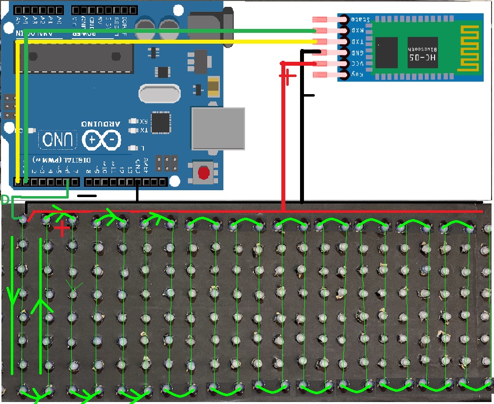
Wiring

How to make pixel led wireless display
arduino-with-bluetooth-and-pixel

Android app

download app – https://bit.ly/32khLlw

download Arduino library – https://drive.google.com/file/d/1VK1yg1hpBcTI9zC48Yir4lYii5kidkNu/view?usp=sharing

Code for How to make pixel led wireless display

#include <Adafruit_GFX.h>
#include <Adafruit_NeoMatrix.h>
#include <Adafruit_NeoPixel.h>
#include <SoftwareSerial.h>
#include <EEPROM.h>

#define PIN 6
#define EEPROM_MIN_ADDR 0
#define EEPROM_MAX_ADDR 100
#define LEN 450

const String defaultText = " Electronics Ravi ";
// temp variable for storing the displayed text
String in = defaultText;

Adafruit_NeoMatrix matrix = Adafruit_NeoMatrix(25, 8, PIN,
  NEO_MATRIX_TOP     + NEO_MATRIX_LEFT +
  NEO_MATRIX_COLUMNS + NEO_MATRIX_ZIGZAG,
  NEO_GRB            + NEO_KHZ800);

SoftwareSerial BTserial(0,1); // RX | TX
const uint16_t colors[] = {
  matrix.Color(255, 0, 0),
  matrix.Color(0, 255, 0),
  matrix.Color(255, 255, 0),
  matrix.Color(0, 0, 255), 
  matrix.Color(255, 0, 255),
  matrix.Color(0, 255, 255)};

void setup() {
  matrix.begin();
  matrix.setTextWrap(false);
  matrix.setBrightness(255);
  matrix.setTextColor(colors[0]);
  randomSeed(analogRead(0));
  BTserial.begin(9600);
  //Serial.begin(9600);
  
  char chararray[LEN];
  if(eeprom_read_string(10, chararray, LEN)) {
    //Serial.println(chararray);
    in = chararray;
  }  
}

void loop() {
  if(BTserial.available() > 0){
    in = BTserial.readString();
    char temparray[in.length()+1];
    in.toCharArray(temparray, in.length()+1);
    if(strstr(temparray, "new") != NULL){
      in = strstr(temparray, "new")+3;
      char temp[in.length()+1];
      in.toCharArray(temp, in.length()+1);
      eeprom_write_string(10, temp);
    }
    else{
      in = defaultText;
      char temp[in.length()+1];
      in.toCharArray(temp, in.length()+1);
      eeprom_write_string(10, temp);
    }
  }
 
  text(random(6));
  
}


void text(int colorbegin){
  int x    = matrix.width();
  int pass = 0;
  while( pass < 3){
    matrix.fillScreen(0);
    matrix.setCursor(x, 0);
    int len = in.length();
    matrix.print(in);
    if(--x < -len*6) {
      x = matrix.width();
      pass++;
      matrix.setTextColor(colors[(colorbegin+pass)%6]);
    }
    matrix.show();
    delay(80);
  }
}

// Input a value 0 to 255 to get a color value.
// The colours are a transition r - g - b - back to r.
uint32_t Wheel(byte WheelPos) {
  WheelPos = 255 - WheelPos;
  if(WheelPos < 85) {
    return matrix.Color(255 - WheelPos * 3, 0, WheelPos * 3);
  }
  if(WheelPos < 170) {
    WheelPos -= 85;
    return matrix.Color(0, WheelPos * 3, 255 - WheelPos * 3);
  }
  WheelPos -= 170;
  return matrix.Color(WheelPos * 3, 255 - WheelPos * 3, 0);
}


//Write a sequence of bytes starting at the specified address.
//Returns True if the entire array has been written,
//Returns False if start or end address is not between the minimum and maximum allowed range.
//If False was returned, nothing was written 
boolean eeprom_write_bytes(int startAddr, const byte* array, int numBytes) {
  int i;
 
  if (!eeprom_is_addr_ok(startAddr) || !eeprom_is_addr_ok(startAddr + numBytes)) return false;
 
  for (i = 0; i < numBytes; i++) {
    EEPROM.write(startAddr + i, array[i]);
  }  return true;
}
 
//Writes an int value to the specified address. 
boolean eeprom_write_int(int addr, int value) {
  byte *ptr;
 
  ptr = (byte*)&value;
  return eeprom_write_bytes(addr, ptr, sizeof(value));
}
 
//Reads an integer value at the specified address
boolean eeprom_read_int(int addr, int* value) {
  return eeprom_read_bytes(addr, (byte*)value, sizeof(int));
}


//Reads the specified number of bytes at the specified address
boolean eeprom_read_bytes(int startAddr, byte array[], int numBytes) {
  int i;
 
  if (!eeprom_is_addr_ok(startAddr) || !eeprom_is_addr_ok(startAddr + numBytes)) return false;
 
  for (i = 0; i < numBytes; i++) {
    array[i] = EEPROM.read(startAddr + i);
  } return true;
}
 
//Returns True if the specified address is between the minimum and the maximum allowed range.
//Invoked by other superordinate functions to avoid errors.
boolean eeprom_is_addr_ok(int addr) {
  return ((addr >= EEPROM_MIN_ADDR) && (addr <= EEPROM_MAX_ADDR));
}
 
//Write a string, starting at the specified address
boolean eeprom_write_string(int addr, const char* string) {
  int numBytes;
  numBytes = strlen(string) + 1;
 
  return eeprom_write_bytes(addr, (const byte*)string, numBytes);
}
 
//Reads a string from the specified address
boolean eeprom_read_string(int addr, char* buffer, int bufSize) {
  byte ch;
  int bytesRead;
 
  if (!eeprom_is_addr_ok(addr)) return false;
  if (bufSize == 0) return false;
 
  if (bufSize == 1) {
    buffer[0] = 0;
    return true;
  }
 
  bytesRead = 0;
  ch = EEPROM.read(addr + bytesRead);
  buffer[bytesRead] = ch;
  bytesRead++;
 
  while ((ch != 0x00) && (bytesRead < bufSize) && ((addr + bytesRead) <= EEPROM_MAX_ADDR)) {
    ch = EEPROM.read(addr + bytesRead);
    buffer[bytesRead] = ch;
    bytesRead++;
  }
 
  if ((ch != 0x00) && (bytesRead >= 1)) buffer[bytesRead - 1] = 0;
 
  return true;
}

video tutorial for How to make pixel led wireless display

DIY Automatic sanitizer Dispenser

Automatic sanitizer Dispenser

DIY Automatic sanitizer Dispenser

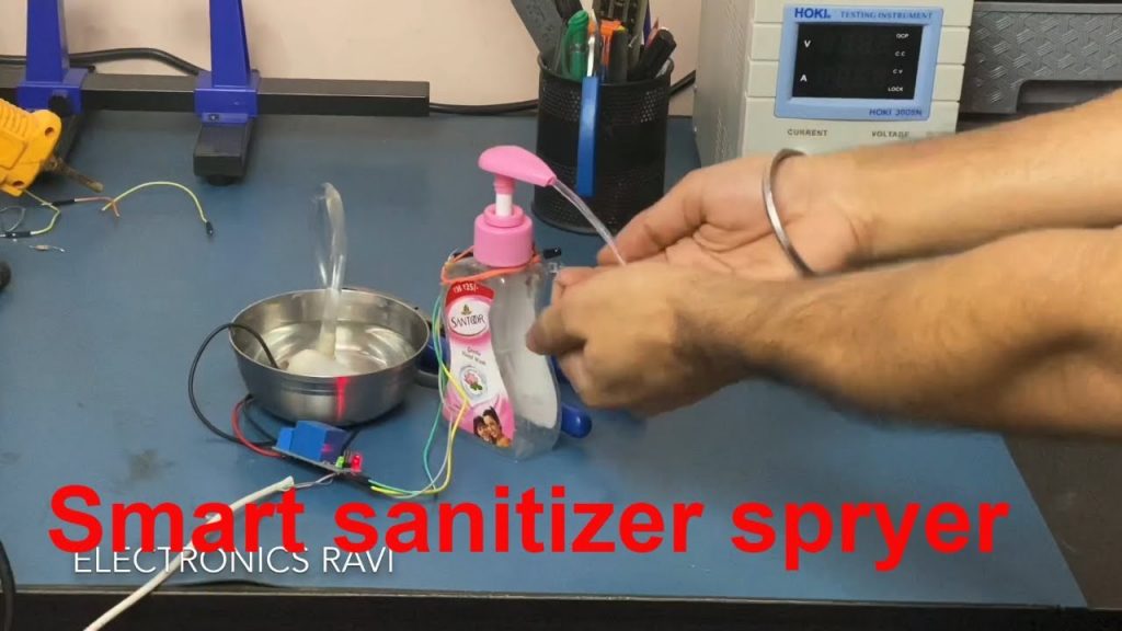
Touchless sanitizer Dispenser drops a controlled amount of sanitizer in your hands when you keep your hand in front of it

material list

Infrared sensor

IMG 20200530 213925

it is an electronics device which have both emitter and receiver also known as IR sensor

this device has an IR transmitter is a led which emits infrared radiations. and the device also had IR Receiver which detects radiation from IR transmitter IR Receiver is a photodiode which converts this light signal into an electrical signal and this signal is amplified by opamp Ic

Working

when you put the hand in front of the sensor light is reflects which is emitted by led and photodiode receive these light and convert into an electrical signal and this signal is processed by amplifier ic and a signal has come in output form and we use this signal to on and off a relay ( electromagnetic switch) and this relay work as a switch so the motor is on and off

Automatic sanitizer Dispenser

video Automatic sanitizer Dispenser

How to make pixel led message display

maxresdefault 4

How to make pixel led message display

I built an 8×30 LED-Matrix pixel led message display with the great RGB LEDs WS2811 The whole matrix is controlled only by one pin of an Arduino Uno

Parts required

Wiring of How to make pixel led message display

How to make pixel led message display

Code for Arduino

// Adafruit_NeoMatrix example for single NeoPixel Shield.


#include <Adafruit_GFX.h>
#include <Adafruit_NeoMatrix.h>
#include <Adafruit_NeoPixel.h>
#ifndef PSTR
 #define PSTR // Make Arduino Due happy
#endif

#define PIN 6

// MATRIX DECLARATION:
// Parameter 1 = width of NeoPixel matrix
// Parameter 2 = height of matrix
// Parameter 3 = pin number (most are valid)
// Parameter 4 = matrix layout flags, add together as needed:
//   NEO_MATRIX_TOP, NEO_MATRIX_BOTTOM, NEO_MATRIX_LEFT, NEO_MATRIX_RIGHT:
//     Position of the FIRST LED in the matrix; pick two, e.g.
//     NEO_MATRIX_TOP + NEO_MATRIX_LEFT for the top-left corner.
//   NEO_MATRIX_ROWS, NEO_MATRIX_COLUMNS: LEDs are arranged in horizontal
//     rows or in vertical columns, respectively; pick one or the other.
//   NEO_MATRIX_PROGRESSIVE, NEO_MATRIX_ZIGZAG: all rows/columns proceed
//     in the same order, or alternate lines reverse direction; pick one.
//   See example below for these values in action.
// Parameter 5 = pixel type flags, add together as needed:
//   NEO_KHZ800  800 KHz bitstream (most NeoPixel products w/WS2812 LEDs)
//   NEO_KHZ400  400 KHz (classic 'v1' (not v2) FLORA pixels, WS2811 drivers)
//   NEO_GRB     Pixels are wired for GRB bitstream (most NeoPixel products)
//   NEO_RGB     Pixels are wired for RGB bitstream (v1 FLORA pixels, not v2)


// Example for NeoPixel Shield.  In this application we'd like to use it
// as a 5x8 tall matrix, with the USB port positioned at the top of the
// Arduino.  When held that way, the first pixel is at the top right, and
// lines are arranged in columns, progressive order.  The shield uses
// 800 KHz (v2) pixels that expect GRB color data.
Adafruit_NeoMatrix matrix = Adafruit_NeoMatrix(30, 8, PIN,
  NEO_MATRIX_TOP     + NEO_MATRIX_LEFT +
  NEO_MATRIX_COLUMNS + NEO_MATRIX_ZIGZAG,
  NEO_GRB            + NEO_KHZ800);

const uint16_t colors[] = {
  matrix.Color(255, 0, 0), matrix.Color(0, 255, 0), matrix.Color(0, 0, 255) };

void setup() {
  matrix.begin();
  matrix.setTextWrap(false);
  matrix.setBrightness(40);
  matrix.setTextColor(colors[0]);
}

int x    = matrix.width();
int pass = 0;

void loop() {
  matrix.fillScreen(0);
  matrix.setCursor(x, 0);
  matrix.print(F("WELCOME TO MY ELECTRONICS RAVI YOUTUBE CHANNEL "));
  if(--x < -400) {
    x = matrix.width();
    if(++pass >= 3) pass = 0;
    matrix.setTextColor(colors[pass]);
  }
  matrix.show();
  delay(100);
}