DIY Ambilight for Desktop

maxresdefault 18

DIY Ambilight for your Desktop

hello, friends welcome to our blogs today we learn how we make our own DIY Ambilight for Desktop It’s a cool project and looks so pretty 

in this project I used WS2812 led strip 93 pieces (you select led to your display size ) 

Component 

Software

Steps

first, we cut the strip according to our display and stick the backside corner of the display and remember the arrow direction on the strip shows in the same direction

ambiant display wiring

Now connect all led strip with a small wire 

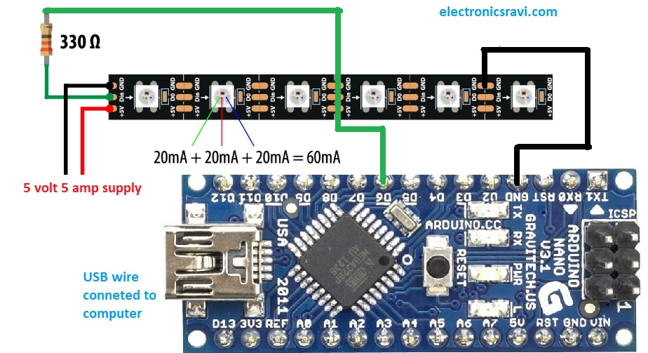
I connect the female connector at the start of the led strip due to the connector I unplug Arduino any time when I need I plug again. the connector has 3 color wire (Red, Green, White )

Red and white is for power supply purpose and Green is for Data 

Arduino code for DIY Ambilight for Desktop

I use Arduino nano if you want to use Arduino Uno code also works I use nano because its size is small.

upload code in Arduino, if you have in ensuring that install, fasted library if all ok your code upload in Arduino in show message of done upload

Wiring

wiring diagram

Software settings

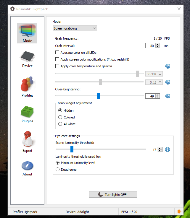
first, install prismatik software and follow these steps as steps given in the video Tutorialls

Screenshot 12

Pixel led data amplifier

pixel led data amplifier

Hello friends welcome to our blog in this blog we learn about how we make Pixel led data amplifiers and also this circuit used as a pixel led data splitter

Why we need pixel led data amplifier

Pixel led data amplifier is used for long-distance data transfer we use different types of pixel controller they transfer data maximum 10 to 20 foot.

if we use long wire our pixel flicker and so we have not good results so we use data amplifier to solve this problem

for Pixel led data amplifier we need a max 485 module

you also make your own module with the help of max 485 ic it’s too cheap and simple to make this type of projects

Pixel led Data Splitter

pixel-led data splitter circuit is used for split data. if you have one controller you want to use 1 controller data in different locations  example if I decorate 1 building and we want the same programme to run on another building simultaneously then we use splitter circuit where we connect the transmitter to the main data controller and connect so many receiver depends own our needs due to this type of connection we save lots of money and all building program look awsome 

Parts required

max 485 module – https://amzn.to/3gZ9T0d

Buy ready-made circuit – https://koshielectronics.com/product/pixel-led-data-amplifier/

Wiring Diagram

Pixel led data amplifier

Video tutorial Pixel led data amplifier

Pixel led Data amplifier circuit use as splitter

Turns ANY Text Into A Natural Lifelike Voice

Led edit 2014

maxresdefault 17

Led edit 2014

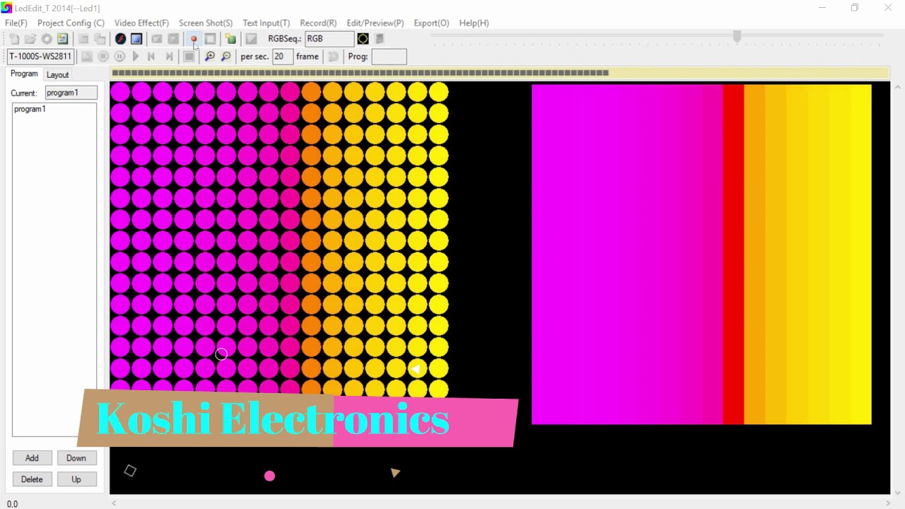
Hello, friends welcome to my blog. In this blog, we learn about How to use Led edit 2014.

Software: Led Edit 2014

Steps to be followed:

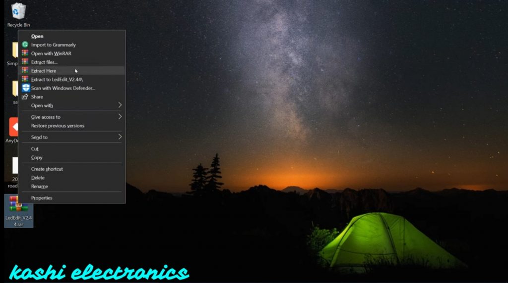
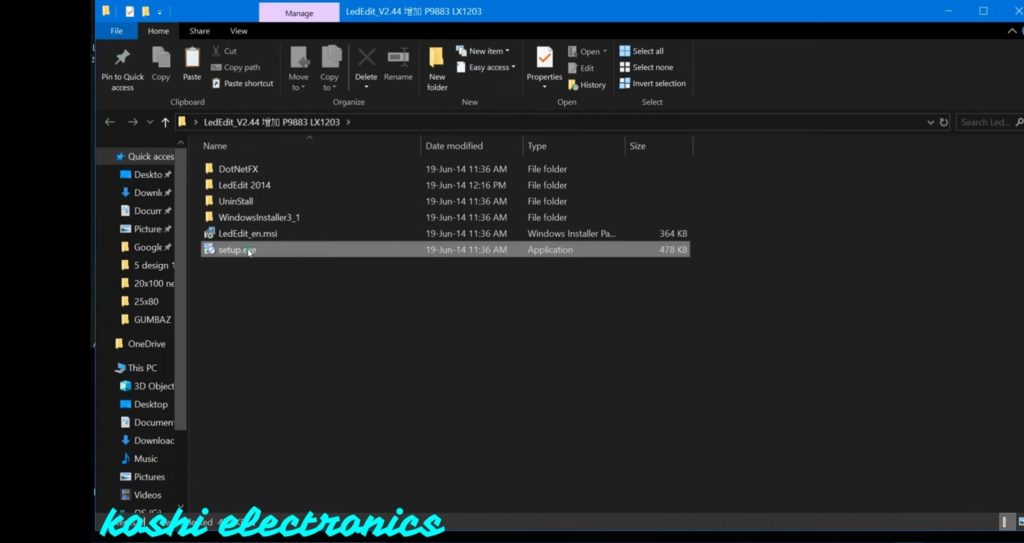
Step 1 If you Already install the software on your computer then right-click on Led Edit 2014 software the click on extract here.

1619690246441

Step 2 After that folder is open. In this folder, we have set up a file option click on that and install it. After that open the software.

1619690246389

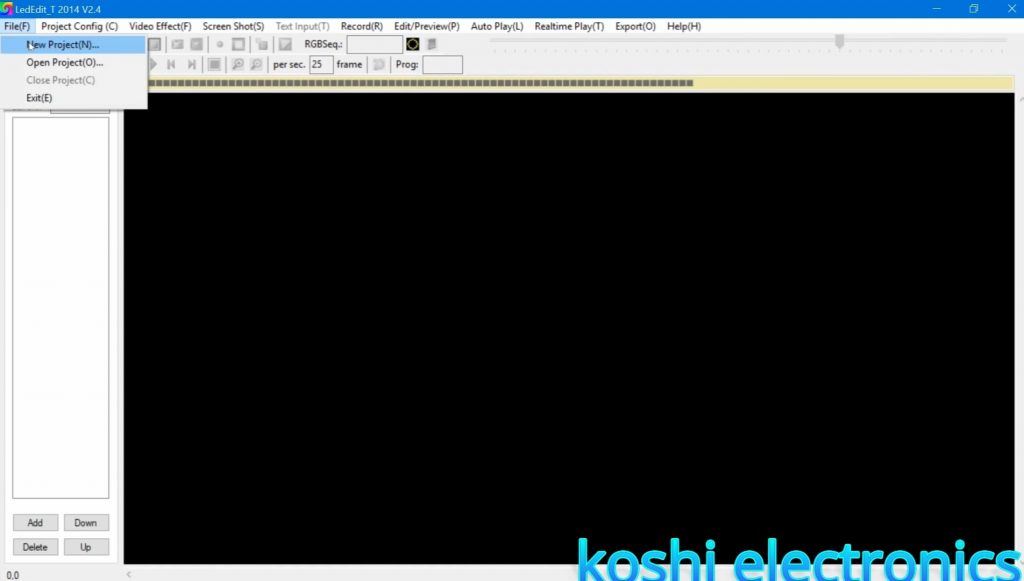
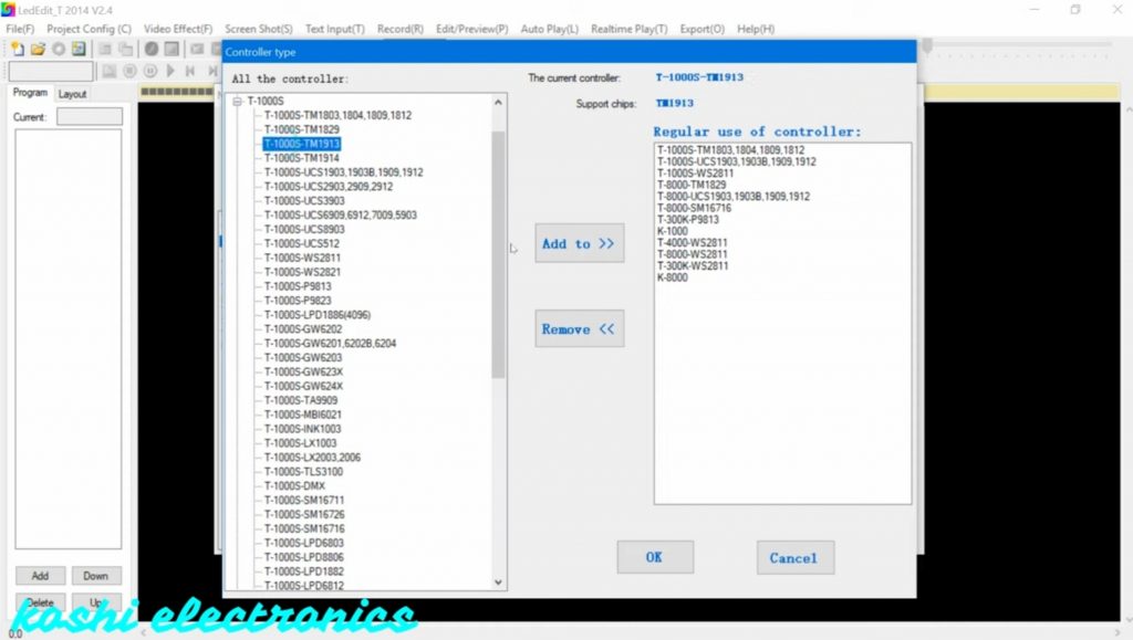
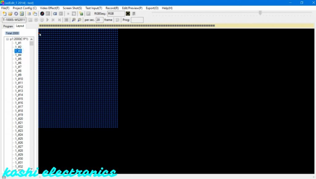
Step 3 Create the new project. Then fix the location of the file where you want to fix it. After that select the controller. If you don’t find the name of the controller then go to select the controller option. Here you can select your controller and after that double click on that, we see that controller is added to the list.

1619679467053 1
1619690246395

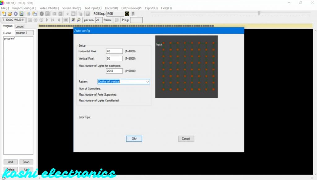
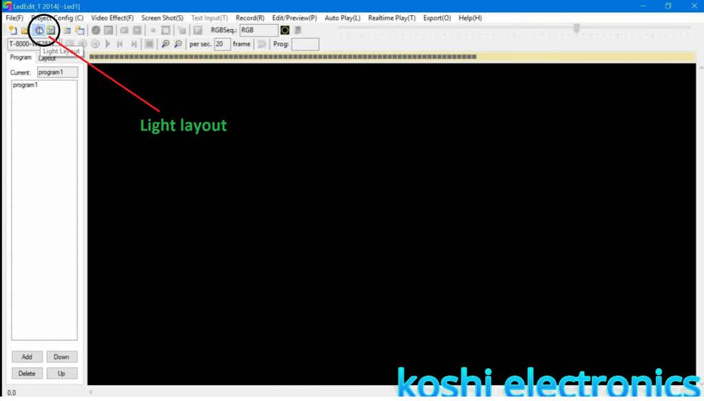
Step 4 After that we go to the light layout Next screen is open, here we enter the details as shown below. Then press ok.

Led edit 2014

Step 5 If you forget where you start wiring then go to layout click on that there is a led list, where you click color changes.

1619690246406

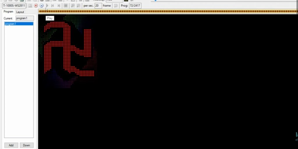
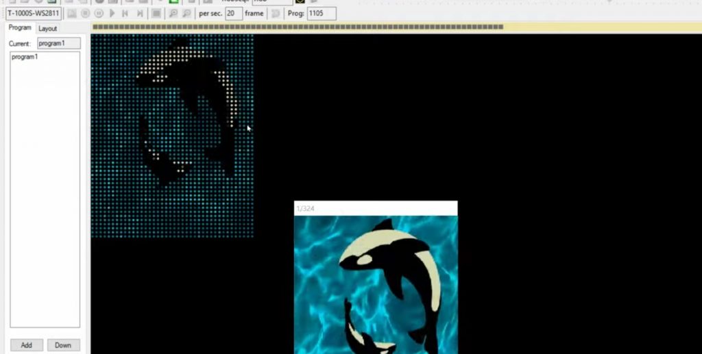
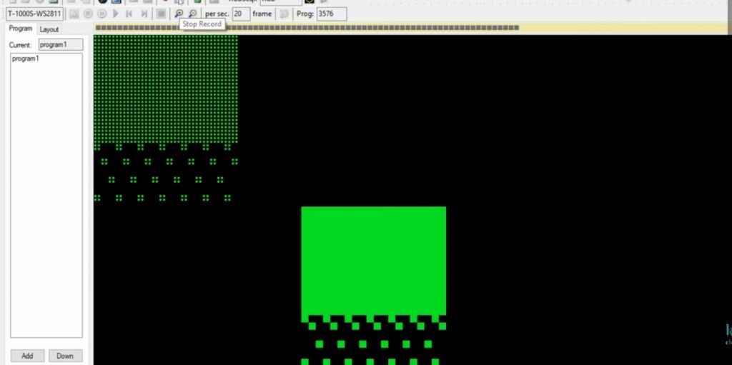
Step 6 After that we open the video. Go to video effect click on the open video then the folder is open. Click on AVR. If you want to save your time click on the fast recording.

1619690246424

Step 7 If you want to record then press on the record button. We see that the recording is on.

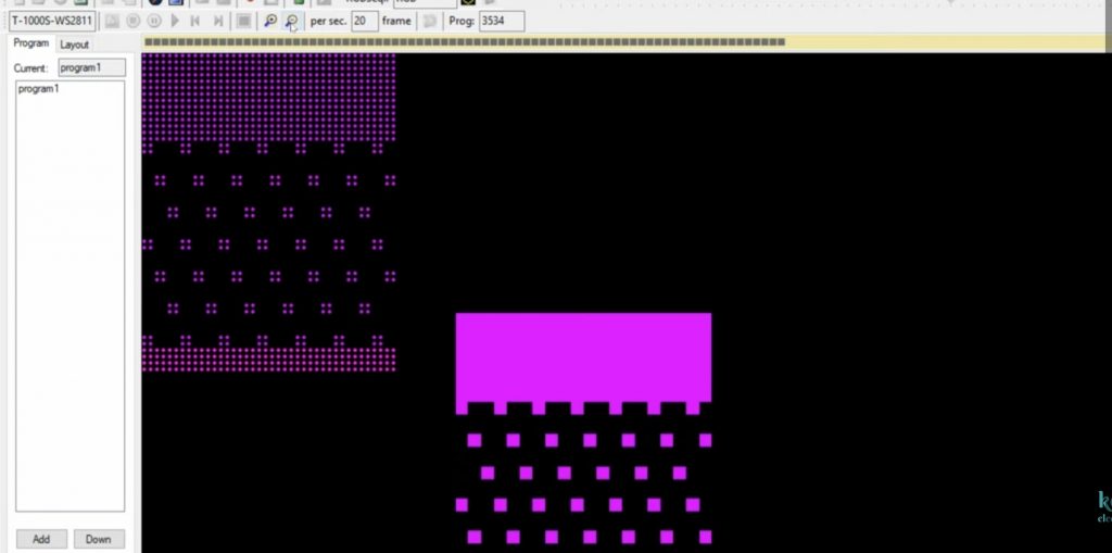
Step 8 Now we also check SWF file, we select the effect. Go to the record option click on the fast recording. We see that fast recording is going on. If you want to record faster then click on F6 and for slow click on F7.

1619690246409

Step 9 For tool file select tool. Go to record click on the fast recording. We see that the recording is done fastly.

Step 10 After that you have to take output. For this click on export. Sometimes the export option is not shown so what you have to do is take some effect record them then export. Suppose we select the AVI effect, we see that some effect is missing so what we have to do is make that effect small. After that, we see no line is missing. After recording the AVI effect then click on stop recording and also press on close video effect. It is very important to do this otherwise the export option is not shown.

1619690246418
1619690246421

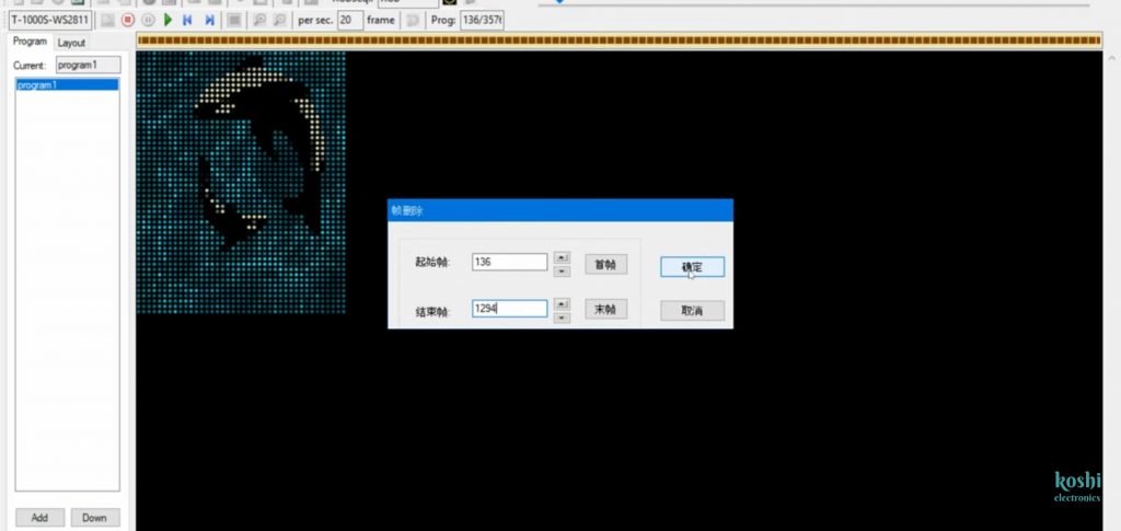
Step 11 If you want to remove some files then click double click on the program we see that effect is running. If you want to remove any effect from that you find out the number where that effect is started and ended. After that go to edit then click on delete upper frame number and lower frame number then press on ok. After this, you see that effect is deleted.

1619690246446

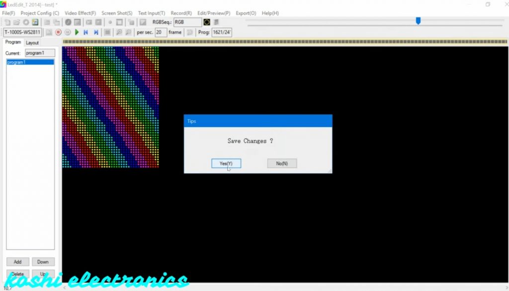
Step 12 After that when you press the stop button, there is a message shown on the screen whether you save changes or not click on yes. If you press on yes the program will change otherwise it will run as it is.

1619690246430 1

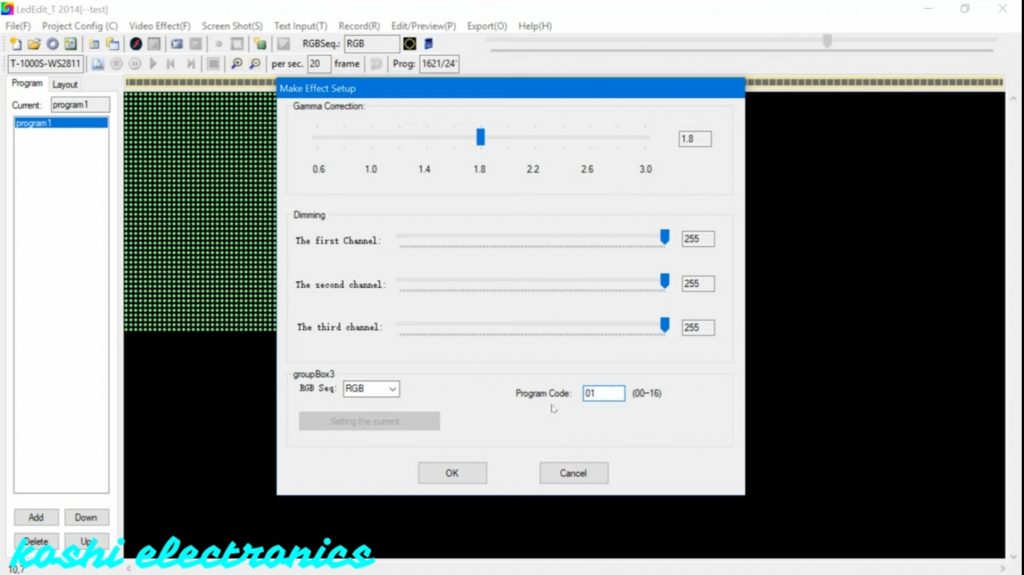
Step 13 Go to the export option click on export open. The next display is shown on the screen here nothing can be changed only we can change the program code. You can enter the program code which program you want to run that code is entered there.

1619690246433

Step 12 After that they will ask that where you want to save the file. According to you, you can choose your file location. Then press on ok. Here program is generated.

Step 13 Open led edit 2014 click on 50*40 folders, open it here we see the program file.

1619690246438 1

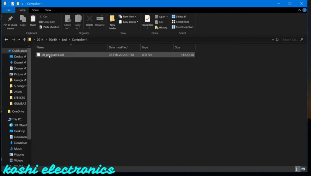
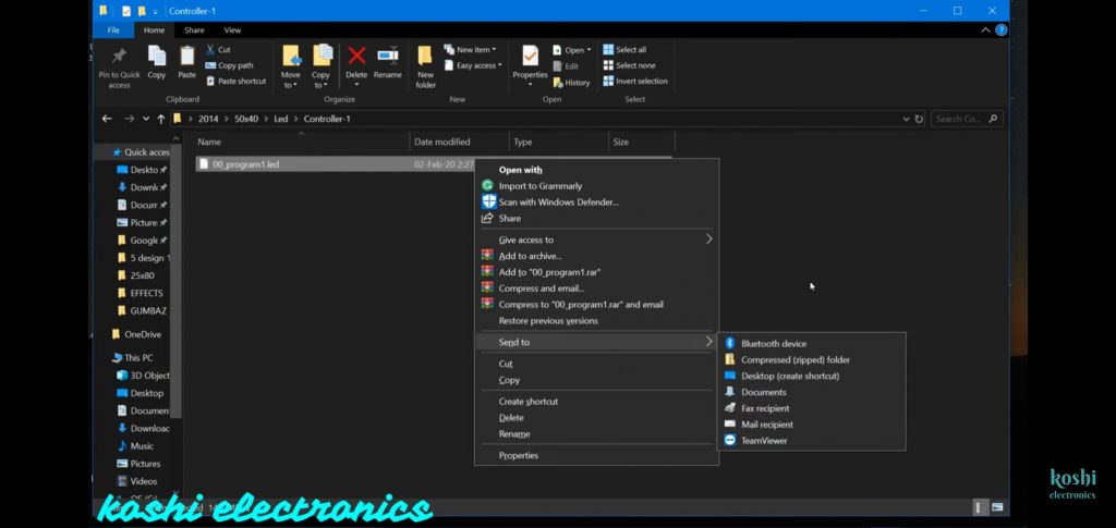
Step 14 After that right-click on program send this program to the memory card which you attached to the system. Before sending the program to a memory card firstly format the card after that send it. When you insert that card on t-1000 the program will run.

1619690246443

How to programme T8000 controller

How to programme T8000 controller

How to programme T8000 controller

Hello, friends welcome to my blog. In this blog, we learn about How to programme T8000 controller.

Software : Led Edit 2014

Steps :

Step 1 Open the Led Edit 2014 software the go to file click on new program.

1619679467053

Step 2 After that select the controller name T-8000. If you did not found the controller name then click on the select controller and select the controller name T-8000-WS2811. Then click on add to. We see that the T-8000-WS2811controller name is added to the list. Then click on OK.

How to programme T8000 controller

Step 3 After that we go to the light layout Next screen is open, here we enter the details as shown below. One thing which we keep on mind that the number of LED’s you have on one port, the same led we will mention there. If we select more number of led’s then design will not run properly. Then click on OK
Untitled 7
1619680123526

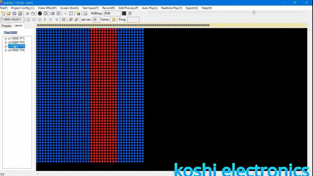
Step 4 On the next screen we see the four different types of color. You can select your own color for each port by clicking on the layout option. After that select accordingly.
1619679467028

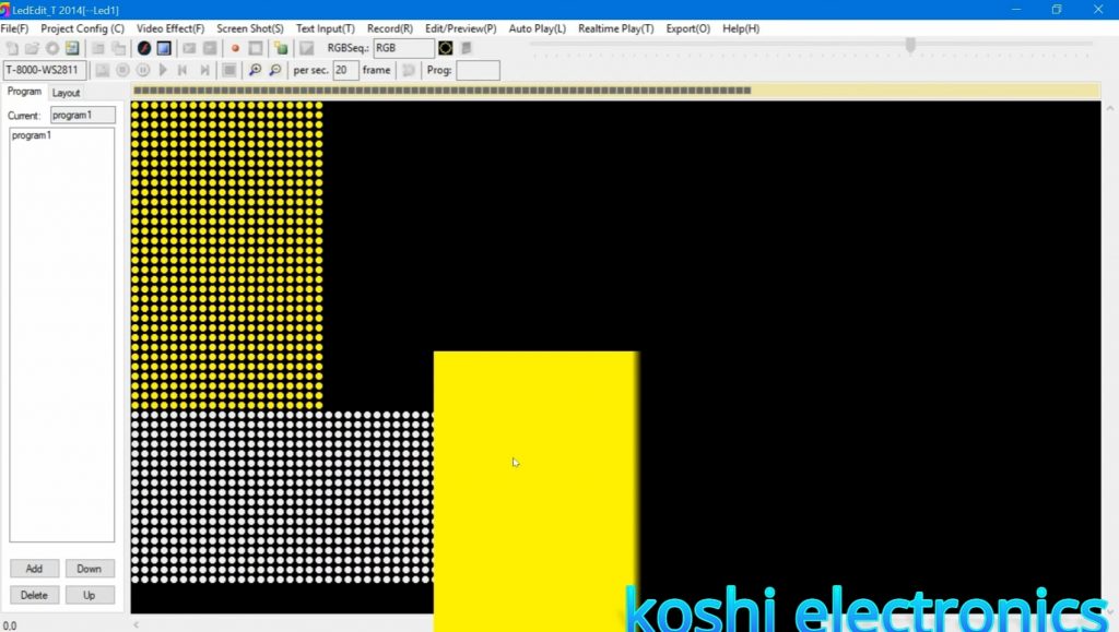
Step 5 Then go to video effect and click on open video. After that select the file of according to you. We see that effect is running half. For this what we have to do is double click on this then move upward and slide it. Then we record it by click on record option.
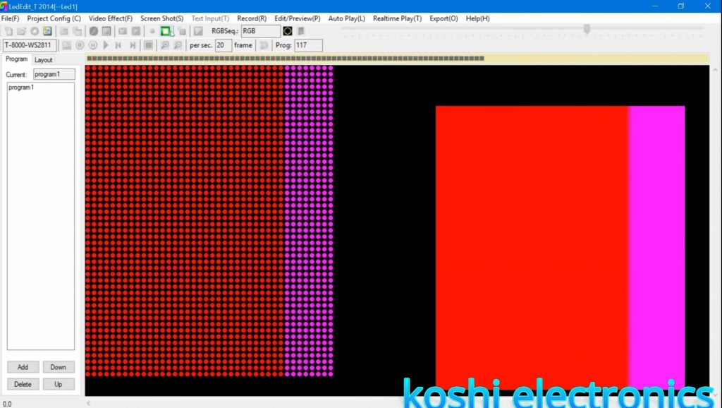
1619679467035
1619679467041

Step 6 If you want to record another effect then first of all you stop the previous recording then go to video effect and click on open video then select the program according to you. Then click on record and record it. After that click on blue button ie.. close video effect button.
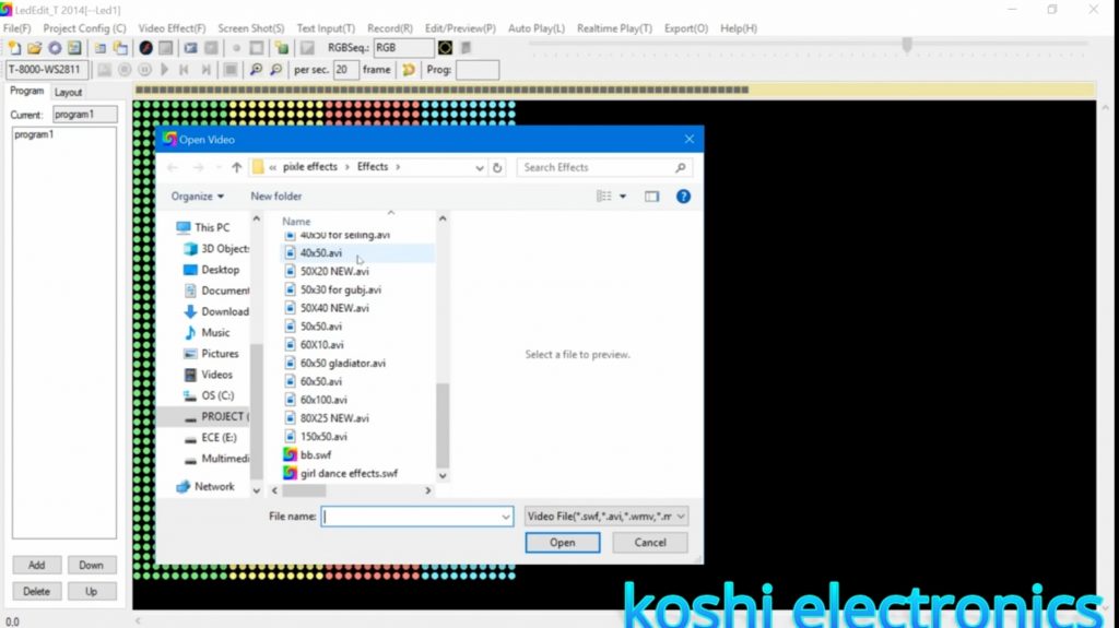
1619679467032

Step 7 Then go to export click on open effect(led). then press ok. After that save the file where you want to save it.We see that the program folder is created where you save the file. Open that folder.
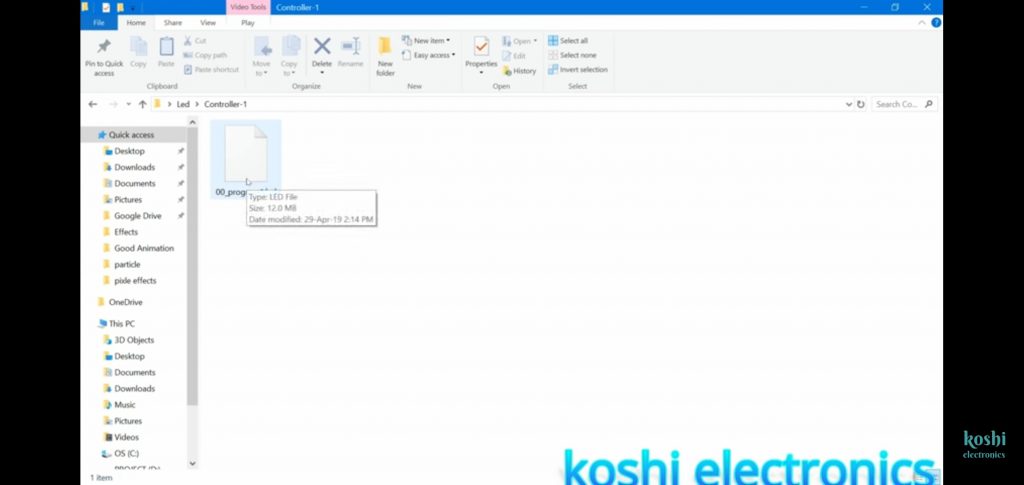
Screenshot 2021 04 29 12 44 33 937 com.google.android.youtube

Step 8 Now we insert the SD card and copy that file on it. Before copying the file on SD card firstly delete the program which is already uploaded on it. After that send file to the SD card which we inserted on.After that we run this on the board.
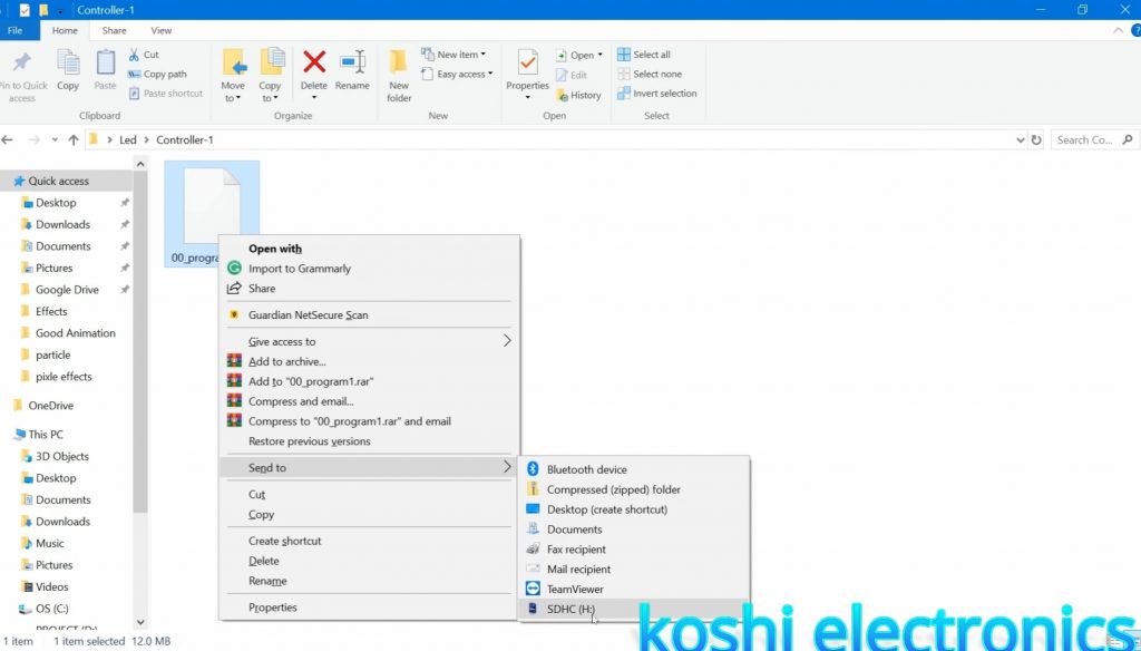
1619679467050

Led edit class not register problem 2021

hqdefault 6

Hello, friends welcome to my blog. In this blog, we learn about how to solve the problem that led edit class not register

Problem: People who have updated their computer or laptop, then the problem is coming with them that their LED edit 2014 is not running and there it is written that the class is not registered. Why did this happen because of the new adobe flash player that came in the window his data has been deleted?

Steps to solve this problem :

Step 1 Search koshielectronic.com in google. After that go to the software section then click on adobe flash player and download it.

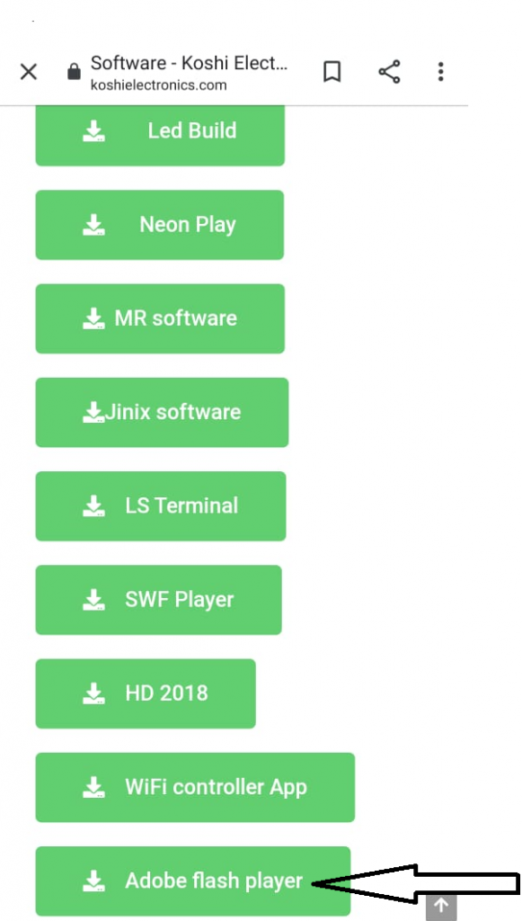
1619265876300
(a)
Led edit class not register
(b)

Step 2 If you are not on our site, then you have to be registered on the site before downloading. So what you have to do is click on register, after that, you have to enter your username and email id then click on register. Login details will be given on your registered email id by which you can log in. You can also change the password according to you. Then go to the software and download it.

1619264955309

Step 3 After completion of download you can run the setup, then icon is created on desktop. After that right click on icon and click on extract here.

1619264955317

Step 4 After extracting two software are created on the screen. First, download first software. After installing this click on the second software to install.

Untitled.png 2

Step 5 After that open the control panel click on uninstall a program. We see the adobe flash player name on it After this, when you open Led edit 2014 then adobe flash player will on, and in Led edit, all effects are run properly.

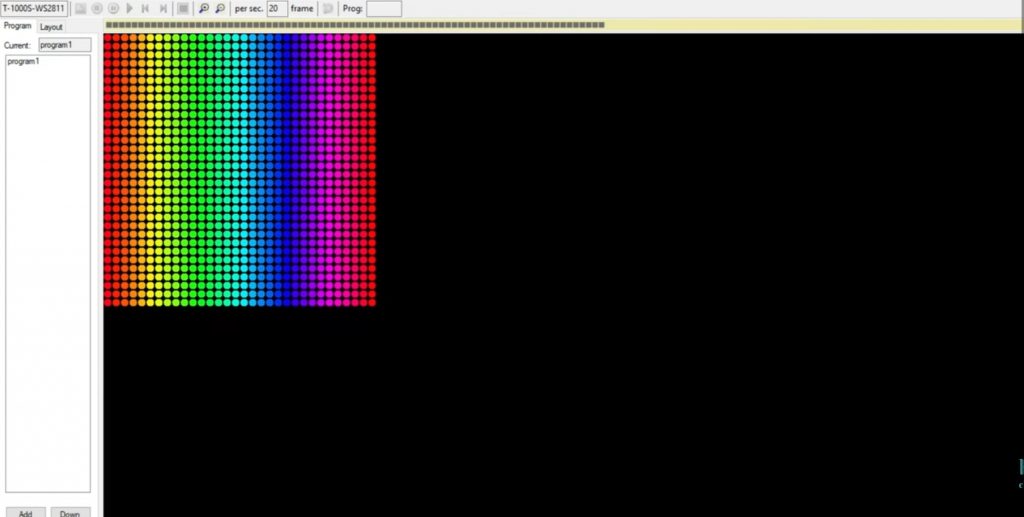
Untitled.png 1
(a)
1619264955332
(b)

video Tutorial – Led edit class not register

how to make pixel led sd card type controller using arduino

pixel led SD card type controller using Arduino

In this projects, we learn about

how to make Pixel led SD card controller using Arduino

Parts required

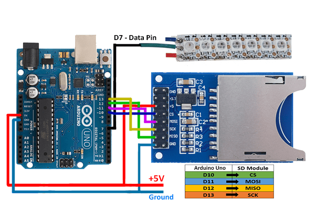
Wiring

Code for How to make pixel led Sd card controller using Arduino

#include "FastLED.h" // add fastled library
#include    // add sdfat library


#define NUM_LEDS 225  // total leds  
#define DATA_PIN 7    // led data pin
CRGB leds[NUM_LEDS];

//SD chip select pin
const uint8_t chipSelect = SS; //chipSelect = 10;

SdFat sd;
SdFile file;


void setup() { 
      // Uncomment/edit one of the following lines for your leds arrangement.
      // FastLED.addLeds<TM1803, DATA_PIN, RGB>(leds, NUM_LEDS);
      // FastLED.addLeds<TM1804, DATA_PIN, RGB>(leds, NUM_LEDS);
      // FastLED.addLeds<TM1809, DATA_PIN, RGB>(leds, NUM_LEDS);
       FastLED.addLeds<WS2811, DATA_PIN, RGB>(leds, NUM_LEDS); // led in use - ws2811 with color sequence RGB
      // FastLED.addLeds<WS2812, DATA_PIN, RGB>(leds, NUM_LEDS);
      // FastLED.addLeds<WS2812B, DATA_PIN, RGB>(leds, NUM_LEDS);
      // FastLED.addLeds<NEOPIXEL, DATA_PIN>(leds, NUM_LEDS);
      // FastLED.addLeds<UCS1903, DATA_PIN, RGB>(leds, NUM_LEDS);
      // FastLED.addLeds<UCS1903B, DATA_PIN, RGB>(leds, NUM_LEDS);
      // FastLED.addLeds<GW6205, DATA_PIN, RGB>(leds, NUM_LEDS);
      // FastLED.addLeds<GW6205_400, DATA_PIN, RGB>(leds, NUM_LEDS);
      
      // FastLED.addLeds<WS2801, RGB>(leds, NUM_LEDS);
      // FastLED.addLeds<SM16716, RGB>(leds, NUM_LEDS);
      // FastLED.addLeds<LPD8806, RGB>(leds, NUM_LEDS);

      // FastLED.addLeds<WS2801, DATA_PIN, CLOCK_PIN, RGB>(leds, NUM_LEDS);
      // FastLED.addLeds<SM16716, DATA_PIN, CLOCK_PIN, RGB>(leds, NUM_LEDS);
      // FastLED.addLeds<LPD8806, DATA_PIN, CLOCK_PIN, RGB>(leds, NUM_LEDS);

     
}

void loop() { 
  
    sd.begin(chipSelect, SPI_FULL_SPEED);
  
  /*******************************************/
  // open first effect file - rainbow.dat
  // file size 70,800 bytes
      //or
  // total leds 118
  // 3 bytes for each rgb color
  // total recorded frames 200
  // 118 x 3 X 200 = 70,800 bytes
  /*******************************************/
  
   file.open("D0.dat", O_READ); 

   for(int i = 0 ;i<200;i++) // 200 frames
  {
    
   file.read((uint8_t*)leds,NUM_LEDS*3); // total bytes(buffer) for each frame 118 x 3 = 354
                         

  FastLED.show();
  delay(40); // delay between each frame 
  }

  file.close();

  
}

Software –

download – https://www.rgbscreenrecorder.com/download.html

after compilation of code make program through screen recorder software and put in sd card and play in your Arduino controller

Video Tutorial

online social media job
Online social media job

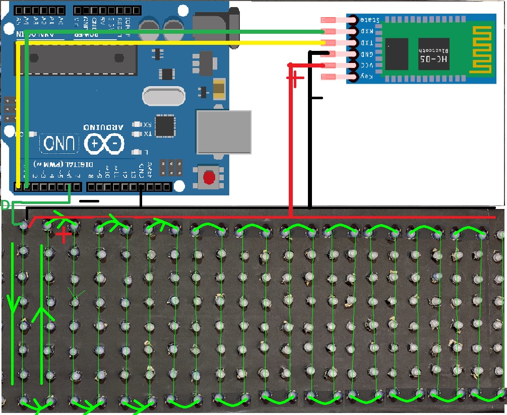
How to make pixel led wireless display

How to make pixel led wireless display


hello friends welcome to my blog in this blog we learn about how to make pixel led wireless display using the android app

Parts required

  • I used the following parts in this project

Wiring

How to make pixel led wireless display
arduino-with-bluetooth-and-pixel

Android app

download app – https://bit.ly/32khLlw

download Arduino library – https://drive.google.com/file/d/1VK1yg1hpBcTI9zC48Yir4lYii5kidkNu/view?usp=sharing

Code for How to make pixel led wireless display

#include <Adafruit_GFX.h>
#include <Adafruit_NeoMatrix.h>
#include <Adafruit_NeoPixel.h>
#include <SoftwareSerial.h>
#include <EEPROM.h>

#define PIN 6
#define EEPROM_MIN_ADDR 0
#define EEPROM_MAX_ADDR 100
#define LEN 450

const String defaultText = " Electronics Ravi ";
// temp variable for storing the displayed text
String in = defaultText;

Adafruit_NeoMatrix matrix = Adafruit_NeoMatrix(25, 8, PIN,
  NEO_MATRIX_TOP     + NEO_MATRIX_LEFT +
  NEO_MATRIX_COLUMNS + NEO_MATRIX_ZIGZAG,
  NEO_GRB            + NEO_KHZ800);

SoftwareSerial BTserial(0,1); // RX | TX
const uint16_t colors[] = {
  matrix.Color(255, 0, 0),
  matrix.Color(0, 255, 0),
  matrix.Color(255, 255, 0),
  matrix.Color(0, 0, 255), 
  matrix.Color(255, 0, 255),
  matrix.Color(0, 255, 255)};

void setup() {
  matrix.begin();
  matrix.setTextWrap(false);
  matrix.setBrightness(255);
  matrix.setTextColor(colors[0]);
  randomSeed(analogRead(0));
  BTserial.begin(9600);
  //Serial.begin(9600);
  
  char chararray[LEN];
  if(eeprom_read_string(10, chararray, LEN)) {
    //Serial.println(chararray);
    in = chararray;
  }  
}

void loop() {
  if(BTserial.available() > 0){
    in = BTserial.readString();
    char temparray[in.length()+1];
    in.toCharArray(temparray, in.length()+1);
    if(strstr(temparray, "new") != NULL){
      in = strstr(temparray, "new")+3;
      char temp[in.length()+1];
      in.toCharArray(temp, in.length()+1);
      eeprom_write_string(10, temp);
    }
    else{
      in = defaultText;
      char temp[in.length()+1];
      in.toCharArray(temp, in.length()+1);
      eeprom_write_string(10, temp);
    }
  }
 
  text(random(6));
  
}


void text(int colorbegin){
  int x    = matrix.width();
  int pass = 0;
  while( pass < 3){
    matrix.fillScreen(0);
    matrix.setCursor(x, 0);
    int len = in.length();
    matrix.print(in);
    if(--x < -len*6) {
      x = matrix.width();
      pass++;
      matrix.setTextColor(colors[(colorbegin+pass)%6]);
    }
    matrix.show();
    delay(80);
  }
}

// Input a value 0 to 255 to get a color value.
// The colours are a transition r - g - b - back to r.
uint32_t Wheel(byte WheelPos) {
  WheelPos = 255 - WheelPos;
  if(WheelPos < 85) {
    return matrix.Color(255 - WheelPos * 3, 0, WheelPos * 3);
  }
  if(WheelPos < 170) {
    WheelPos -= 85;
    return matrix.Color(0, WheelPos * 3, 255 - WheelPos * 3);
  }
  WheelPos -= 170;
  return matrix.Color(WheelPos * 3, 255 - WheelPos * 3, 0);
}


//Write a sequence of bytes starting at the specified address.
//Returns True if the entire array has been written,
//Returns False if start or end address is not between the minimum and maximum allowed range.
//If False was returned, nothing was written 
boolean eeprom_write_bytes(int startAddr, const byte* array, int numBytes) {
  int i;
 
  if (!eeprom_is_addr_ok(startAddr) || !eeprom_is_addr_ok(startAddr + numBytes)) return false;
 
  for (i = 0; i < numBytes; i++) {
    EEPROM.write(startAddr + i, array[i]);
  }  return true;
}
 
//Writes an int value to the specified address. 
boolean eeprom_write_int(int addr, int value) {
  byte *ptr;
 
  ptr = (byte*)&value;
  return eeprom_write_bytes(addr, ptr, sizeof(value));
}
 
//Reads an integer value at the specified address
boolean eeprom_read_int(int addr, int* value) {
  return eeprom_read_bytes(addr, (byte*)value, sizeof(int));
}


//Reads the specified number of bytes at the specified address
boolean eeprom_read_bytes(int startAddr, byte array[], int numBytes) {
  int i;
 
  if (!eeprom_is_addr_ok(startAddr) || !eeprom_is_addr_ok(startAddr + numBytes)) return false;
 
  for (i = 0; i < numBytes; i++) {
    array[i] = EEPROM.read(startAddr + i);
  } return true;
}
 
//Returns True if the specified address is between the minimum and the maximum allowed range.
//Invoked by other superordinate functions to avoid errors.
boolean eeprom_is_addr_ok(int addr) {
  return ((addr >= EEPROM_MIN_ADDR) && (addr <= EEPROM_MAX_ADDR));
}
 
//Write a string, starting at the specified address
boolean eeprom_write_string(int addr, const char* string) {
  int numBytes;
  numBytes = strlen(string) + 1;
 
  return eeprom_write_bytes(addr, (const byte*)string, numBytes);
}
 
//Reads a string from the specified address
boolean eeprom_read_string(int addr, char* buffer, int bufSize) {
  byte ch;
  int bytesRead;
 
  if (!eeprom_is_addr_ok(addr)) return false;
  if (bufSize == 0) return false;
 
  if (bufSize == 1) {
    buffer[0] = 0;
    return true;
  }
 
  bytesRead = 0;
  ch = EEPROM.read(addr + bytesRead);
  buffer[bytesRead] = ch;
  bytesRead++;
 
  while ((ch != 0x00) && (bytesRead < bufSize) && ((addr + bytesRead) <= EEPROM_MAX_ADDR)) {
    ch = EEPROM.read(addr + bytesRead);
    buffer[bytesRead] = ch;
    bytesRead++;
  }
 
  if ((ch != 0x00) && (bytesRead >= 1)) buffer[bytesRead - 1] = 0;
 
  return true;
}

video tutorial for How to make pixel led wireless display